

BRIDGE MANUFACTURING TECHNOLOGY FOR CNC MACHINE
Ivan Sigurnjak, Radojka Marković, Dejan Marić, Antun Stoić, Josip Cumin, Miroslav Duspara, Ivan Samardžić, Branko Grizelj
JJ Strossmayer University in Osijek, Faculty of Mechanical Engineering in Slavonski Brod
Keywords: Technology, bridge, CNC machine, laser, cutterm>
Abstract/strong>
The paper describes the purpose and principle of operation of the machine, technical characteristics and requirements, used manufacturing technologies, cost estimates and necessary documentation.
For the production, it is necessary to provide the necessary technical documentation, choose the material and be well versed in all the technologies that were used, so that the production of parts is as favorable as possible, with the requirements and tolerances achieved.
In addition to standard technologies such as saw cutting, grinding, welding, sandblasting, surface protection, new production technologies were also used, such as milling, drilling and countersinking on numerically controlled machines, and water jet cutting.
All technologies are covered, from cutting and preparation of materials to product assembly.
p>1. INTRODUCTION
The manufactured bridge is intended for a CNC laser cutting machine. It can also be used for other cutting methods, such as water, gas and plasma cutting. It is necessary to achieve high positioning accuracy due to a very thin cut, about 0.3 mm thick. The bridge must also have great stiffness due to the high speedsand movements of up to 80 m/min (Figure 1.1).
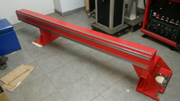
Fig. 1 CNC laser cutter bridge/p>
Laser cutters are characterized by high performance, good quality of cutting surfaces and cutting speed. Almost all metals can be cut with this process. The external dimensions of the machine are 3700x2000 mm, and the dimensions of the work table are 2575x1300 mm, which is enough to work with sheets of standard dimensions 1250x2500 mm. The maximum possible cutting thicknesses are 10 mm for "black" steels and 6 mm for stainless steels. The machine can cut pipes of round, square and rectangular profiles, with a maximum diameter of 100 mm for round and 100x100 mm for square sections. The highest speed that can be achieved on the machine is 80 m/min, while the maximum cutting speed of the machine is 20 m/min for sheets with a thickness of 1 mm.
Accuracy and the positioning repeatability of the cutter head is 0.08 mm. The biggest challenge when making machines like a laser cutter is precisely achieving high accuracy with high cutting speeds, which significantly affects the cost of making individual parts.
>
2. CREATION OF TECHNICAL DOCUMENTATION FOR CNC MACHINE/strong>
Models and technical documentation were created in the computer program Solidworks (Figure 3.1, Figure 3.2). 3D models of objects of various shapes are easily created. It is easy to get 2D drawings from the created model with all the data needed for creation. It is also zgreatly facilitated work when creating programs for processing on CNC machines. In this case too, a computer model was used to create programs and g-code for machining with multiple tools on a machining center (Figure 3.3). It is a feature of modern preparation that makes work much easier, reduces the possibility of mistakes, affects economy and competitiveness on the market. Technical documentation created in this way is easy to save, and can be used and modified in case of later creation of such or a similar assembly.
ps://www.sigmat.hr/img/cms/strucni-clanci/solidwords-3d-model-mosta.jpg" alt="" width="651" height="291" />
Figure 2 Solidworks 3D model of the bridge

Figure 3 Solidworks 3D laser cutters/p>
3. MAG WELDING
Electric arc welding with a metal fusible electrode in a protective gas atmosphere belongs to fusion welding procedures. The MAG procedure (metal active gas) welding takes place in a protective atmosphere of active gas CO2 or a mixture with a predominant proportion of CO2. In practice, the Mag process is often called the CO2 process. Shielding gases must be used to protect the electric arc and molten material from the surrounding atmosphere. The formation of an electric arc occurs between the electrode, mostly connected to the + pole of the direct current source, and the basic msterial. For stable maintenanceit is not possible to use alternating current in the port due to weak ionization. [1]
The heat generated in the electric arc leads to the melting of the basic and additional material. The wire has the function of electrode and additional material. This process is often used as an automatic, semi-automatic or robotic process. In the robotic process, the welder only monitors the operation of the machine, while the parameters are previously defined. In semi-automatic procedures, the addition of wire is mechanized, while welding is performed manually. Automatic procedures are managed mechanically, but without the use of robots.
In the metal industry, semi-automatic processes are most often used due to their simplicity and flexibility. The only difference between the MIG and MAG process is the use of different protective atmospheres.[1]
Assocor electricity must be connected to the electrical network from which it receives energy. The welding current is supplied from the source by conductors, one of which is connected to the workpiece, and the other to the welding gun via the control distribution unit. Through the contact conductor located in the gun, the electric current passes through the welding wire, which is automatically unwound at a uniform speed by means of an electric motor, and is added to the electric arc through the gun. Shielding gas from the bottle comes to the welding site through the nozzle of the gun. It also passes through the control unit of the machine (Figure 4.3). Protective gas is blown into the harbor atmosphere through a nozzle. The contact wire is a consumable part in this welding process. Herand the role is to conduct current to the wire and guide it. The nozzle is used to direct the shielding gas towards the arc, and is also one of the consumable parts. Due to frequent changes, they are easily changed. Welding guns can be cooled by water or air, depending on the amount of heat generated during operation. [1]
PrBefore starting welding, it is necessary to adjust the gas supply and welding parameters. In semi-automatic welding, the gun is brought to the work piece, to the place where the welding starts, and by pressing the button on the gun, the establishment of the electric arc, the addition of wire and protective gas is initiated. Gas is added by opening the solenoid valve, and this happens before the wire exits the contact lead. An electric arc is established by closing the circuit when the wire touches the workpiece. Then the gun is moved using a specific welding technique, in the required direction.
Speed weldivation depends on numerous conditions, mostly on the thickness and type of basic and additional material. The formation of an electric arc causes the melting and mixing of the basic and additional material, they are joined and a welded joint is formed by solidification. [1]

Figure 4 Schematic representation of the device (a) and the MIG/MAG welding process (b) [1]/p>
Current sources are constantly improved in order to be able to adjust the parameters as best and precisely as possiblethree welding. Current sources can be transistor and thyristor. Transistors are technologically more advanced due to simpler regulation of parameters. On most new devices, it is possible to determine other parameters automatically, based on a known one. [1]